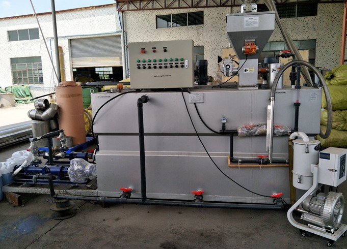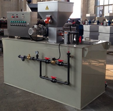
Preparation syatems
Construction Features
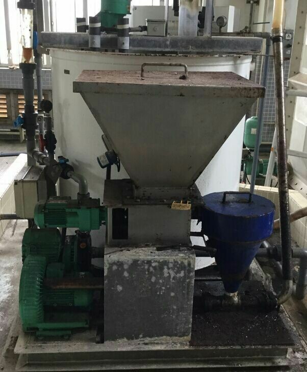
■Variable capacity powder dosing unit, hopper with powder level indicator worm screw with bridge breaker scrapers
■water inlet and adjustment unit ,solenoid vale, pressure switch, disperser nozzle
■Preparation tank with covers, divided into three sectors for dissolving, maturing and storage
■Control and electrical command switchboard including the automatisms and indicators for fully automatic plant operation
■Solution dosing system, generally consisting of dosing pumps selected from the numerous versions available from our range (ask for the specific catalogue)
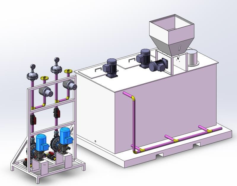
Operating Principles
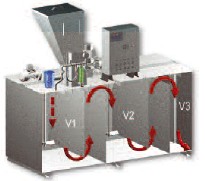
The preparation tank is divided into three sector: dissolving V1,maturing V2 and storage V3,interconnected by siphons that form a preferential path necessary for the formation of a top quality solution. The powder form the dosing unit is mixed with water ,which ,appropriately sprayed ,from a nozzle, carried out the important action of dispersion.
The water/Powder mixture then drops into the tank below where the dissolving phase begins. In dissolving sector V1 a slow agitator keeps the contents of the tank in movement ,thus favoring homogenization of the solution.
The siphon transfers the solution to the maturing sector V2 where another slow agitator keeps it homogeneous until maturing is complete. Then the solution is transferred to storage sector V3 from which it can be transferred for use.
The level switches installed it this sector control the systems automatic functions:
High and normal level switch: when the solution reached the high level this switch stops the powder dosing unit and closes the water inlet solenoid valve. In the normal level position it enables dosing unit functioning and opens the water solenoid valve.
Low level switch: when the solution falls to minimum level this switch stops the dosing pump and lights up an alarm indicator on he electrical switchboard.
Options
■Heating of dosing unit discharge pipe
■Automatic dosing pump adjustment
■Overflow and drain header
■Powder minimum level switch
■water pressure reducer
■PLC programmable electrical switchboard
■Third agitator in the storage section
■Pneumatic powder loading
|
Model |
Max apacity L/H |
Screw Feeder L/H |
Size(m) |
Mixer |
Total power consumption (KW) |
||
|
Qty |
Speed (RPM) |
Power(KW) |
|||||
|
PL-1000 |
1000 |
4
|
1.7*1.31*2.22 |
2 |
120 |
0.37 |
1.5 |
|
PL-1500 |
1500 |
2.04*1.66*2.22 |
2 |
120 |
0.37 |
1.5 |
|
|
PL-2000 |
2000 |
2.221*1.7*2.31 |
2 |
120 |
0.37 |
1.5 |
|
|
PL-3000 |
3000 |
16
|
2.54*1.85*2.46 |
2 |
200 |
0.37 |
1.5 |
|
PL-4000 |
4000 |
3.28*1.79*2.42 |
2 |
200 |
0.75 |
2.2 |
|
|
PL-5000 |
5000 |
3.57*1.90*2.73 |
2 |
200 |
1.5 |
4 |
|
|
PL-6000 |
6000 |
3.2*2.12*2.82 |
2 |
200 |
1.5 |
4 |
|
|
PL-8000 |
8000 |
24 |
4.65*2.02*2.84 |
2 |
220 |
1.5 |
4 |